A simple Cisco network with two routers
Overview
This walkthrough explains an easy way to set up a simple network: two routers, each with a switch and a PC host. This will require several IP address configurations as well as an explicit route configuration on each router.
Topology
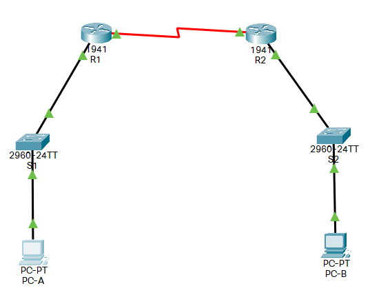
We use the following network topology:
| Node | Interface | IP Address | Subnet Mask | Default Gateway |
|---|---|---|---|---|
| Host B (PC-B) | NIC | 192.168.1.10 | 255.255.255.0 | 192.168.1.1 |
| Router 2 | G0/1 | 192.168.1.1 | 255.255.255.0 | N/A |
| Router 2 | S0/0/0 | 10.1.1.2 | 255.255.255.252 | N/A |
| Router 1 | S/0/0/1 | 10.1.1.1 | 255.255.255.252 | N/A |
| Router 1 | G0/1 | 192.168.0.1 | 255.255.255.0 | N/A |
| Host A (PC-A) | NIC | 192.168.0.10 | 255.255.255.0 | 192.168.0.1 |
The serial connections are bold so they stand out against the subnets. The switches are left unconfigured, so they are not listed in the table. (In fact, if you removed the switches, the network would operate the same way.)
Set up the devices and connections
This section will set up the “physical” components only. The next section will configure IP addresses and routes for all endpoints.
Start by setting up the routers, switches, and hosts as shown in the previous topology. (A better-quality image is also provided at the end of this guide.) The serial connection should use the DCE cable.
Installing the serial component
Each router needs a “physical” component installed as well: the HWIC-2T. This allows serial connections between the two routers.
The component is shown in this screenshot.
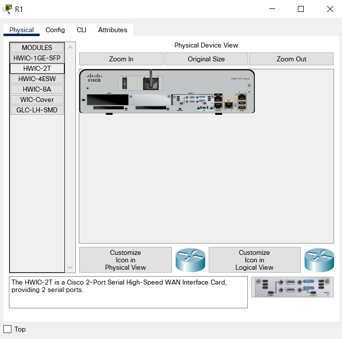
Note: You can click on any physical component from the list to display its description at the bottom.
In this example, you can see it already installed (near the two ethernet ports to the right).

Installing it is easy. First, turn off the router by clicking the black I/O button on the physical device. This is the small rectangle to the right of the “CISCO” icon on the router’s image.
Once the router is off, drag the “HWIC-2T” from the list in the left-hand panel. Place it in an open slot. In the previous screenshot, you can see open slots as the larger, horizontal rectangles. The HWIC-2T is installed in the far right slot, next to the two ethernet ports.
Once installed, turn on the router by clicking the I/O button. The router may take a few moments to boot.
Configuring the hosts
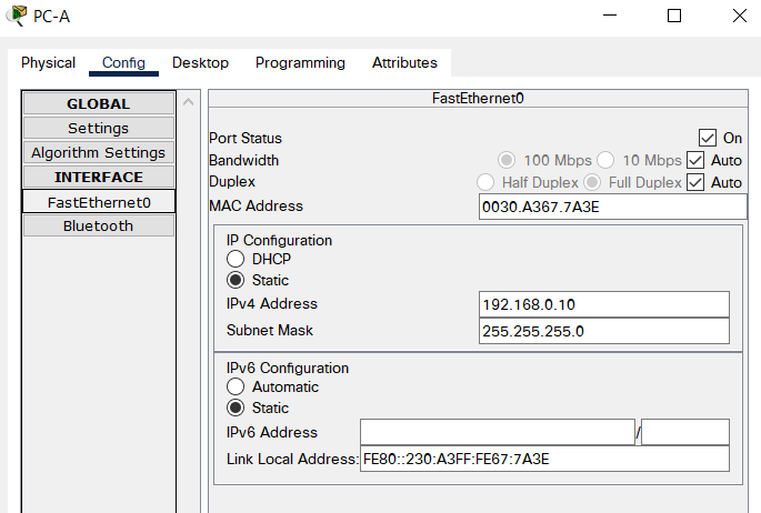
Each host need only its static IP values: the IP address, subnet mask, and gateway. Let’s use Host A as an example.
The IPv4 address and Subnet Mask for the FastEthernet0 device:
And the Default Gateway in the Global Settings:
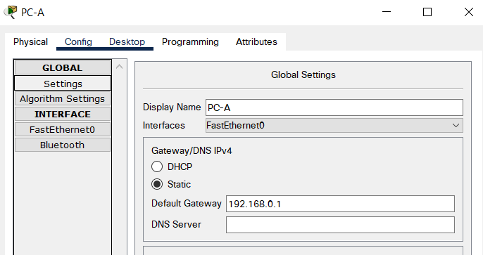
Repeat the process with the correct values for Host B.
Configuring the routers
As shown in the topology map, each router needs to connect to its own switch and to the other router. The switches are left unconfigured in this guide. So, you can think of each router as connecting directly to its own host.
With that in mind, each router needs two connections:
- Serial connection on
s0/0/0, which connects to the other router. - Gigabit connection on
GigabitEthernet0/1, which connects to its switch (and, really, its host PC)
In addition, you will need to set an explicit route to the next router’s subnet. We walk through this as the final step of this section.
Configure the serial connection
The serial cable connects the two routers. Because we are only connecting two devices, we can use 252 in the subnet mask for this connection.
Note: prior to setup, if you run show ip interface brief, it appears as administratively down.
Configure it like:
interface serial0/0/0
no shutdown
description "Connection to Router1"
ip address 10.1.1.2 255.255.255.252
Its settings in the GUI:
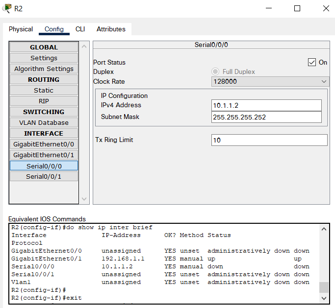
Note: At this point, the connection is still down. But, it has changed to down (not administratively down). You can see this in the screenshot.
To make the connection, configure the other router in the same manner: using 10.1.1.1 255.255.255.252. However, do not set the clock rate on the other one. The clock setting in the first router will work fine.
After the IP address and no shutdown settings are applied, the connection should turn green. If not, try removing the DCE cable and reattaching to each s0/0/0 port.
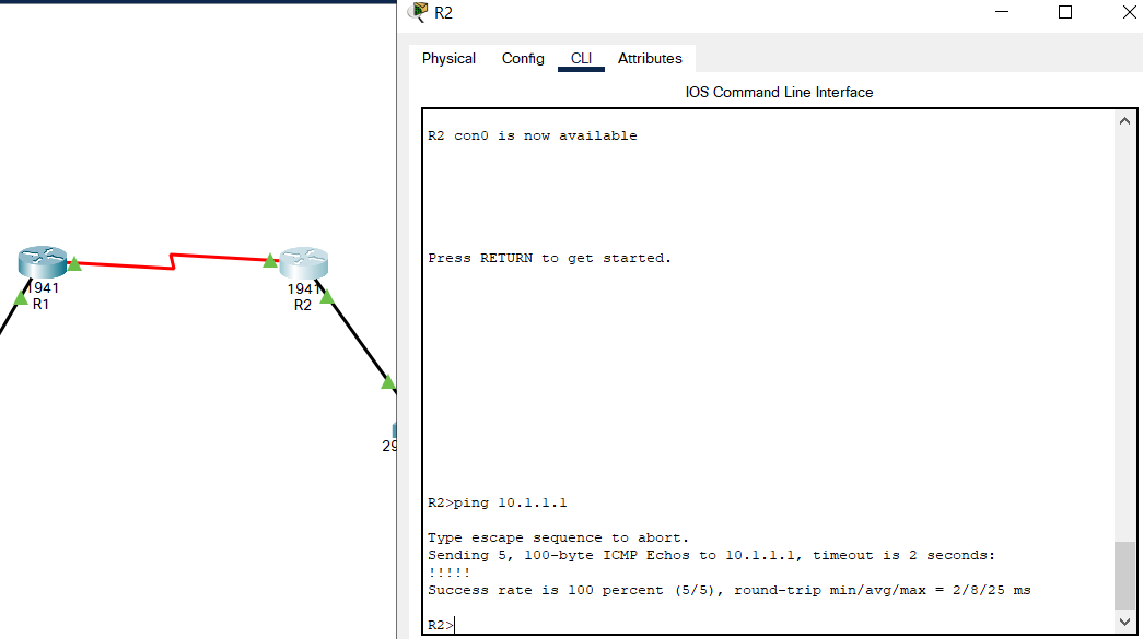
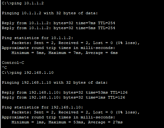
A successful connection has a green triangle on each router. In addition, each router should successfully ping each other.
Configure the Gigabit ethernet connections
config terminal
no ip domain-lookup
interface gigabitethernet0/1
no shutdown
description "Connection to Switch1"
ip address 192.168.1.1 255.255.255.0
Router 1’s configuration from the GUI:
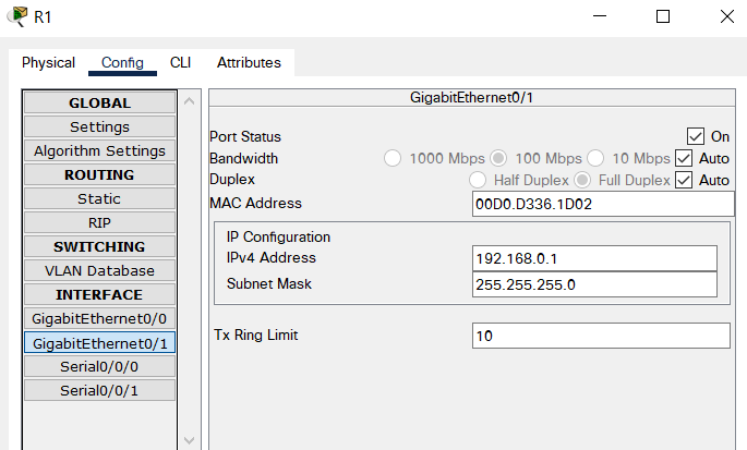
On the other router, repeat these steps, but use the correct IP for that subnet. We will use 192.168.1.1 255.255.255.0 for this.
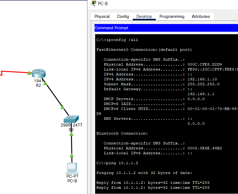
If successful, each Host can successfully ping their Gateway (the router closest to them). In this screenshot, Host B can ping its gateway, Router 2.
Set up routes between hosts
This is the final step and should connect Host A to Host B.
At this point, each router can ping the other: by using their 10.1.1.0 connection. However, neither router can ping anything behind the other’s 192.168 gateways. In addition, the Host PCs cannot ping the other router, either.
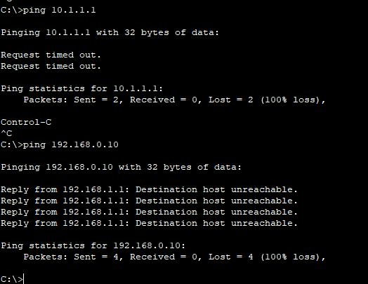
We fix this by setting up a route.
In the command line, we can use a simple recursive route. This is just enough for each host to interact with each other (or anything on the other network).
The command syntax is:
ip route <Network> <Mask> <Next Hop>
Where:
- Network is the other subnet’s IP, but with a zero (
0) instead of the trailing1 - Mask is just the other’s subnet mask
- Next Hop is the IP address of the serial connection’s gateway on the other router
Let’s start with Router 2:
- Network:
192.168.0.0(the subnet behind Router 1) - Mask:
255.255.255.0 - Next Hop:
10.1.1.1
The full command in Router 2 looks like:
ip route 192.168.0.0 255.255.255.0 10.1.1.1
This makes a new entry in Router 2’s routing table.
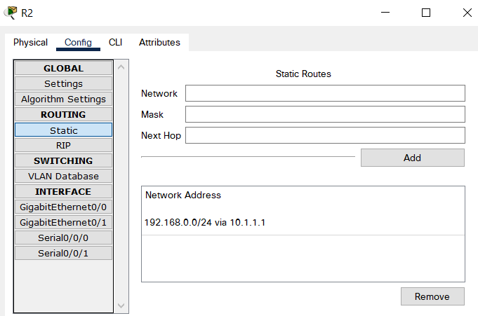
Note: You can also enter the routing information here instead of using the command line.
Now, got to Router 1. Create a route with the following values:
- Network:
192.168.1.0 - Mask:
255.255.255.0 - Next Hop:
10.1.1.2
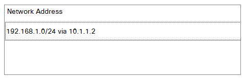
ip route 192.168.1.0 255.255.255.0 10.1.1.2
The entry now appears in Router 1:
Test the connections
Try to ping the other router and other host for each subnet.
On Host B:
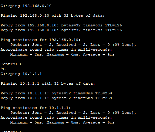
And on Host A:
Once each host can ping the other gateway and other host, the network has connectivity. All lights should appear green and all ping commands should succeed for all endpoints.
References
Initial video: https://www.youtube.com/watch?v=MBG0ZOhFBDE
Destination Host Unreachable and routing: https://www.youtube.com/watch?v=DVV_0nKl30Q